
The Expan'Son is an expansion board that adds 16 channels to your Ambi'Son, or to an Arduino, an ESP32 or a Raspberry Pi. Each channel works as an input (a button, a contact, a sensor) or as an output (an LED, an order sent to a relay). It is sold in the BigSoundBank shop.
Everything goes through the I2C bus: two shared communication wires, plus the power supply. You can connect up to 8 in a chain, i.e. 128 channels, without using any other pins of your board.

Overview
I designed this board for my Cadavre Exquis Sonore (in French), an installation with 32 illuminated buttons, then made it versatile enough for other projects that need lots of buttons and lights. I design and solder it myself.
- It is built around an MCP23017, a chip that gives a microcontroller 16 extra pins.
- Each channel has its own screw terminal (the channel and its ground) and a 330 Ω resistor already soldered.
- It is powered at 3.3 or 5 V, the voltage of the board that drives it, through the same cable as the bus.
- It comes fully soldered, with a ribbon cable to connect it to the Ambi'Son or to the previous board, but without push buttons.
- Since V2, it has exactly the Ambi'Son's format: same size, same corners, same four mounting holes. So they can be stacked.
Whether you are a user or a tinkerer, feel free to contact me if you have any questions about it!
Warning
Caution: the board comes without a case. Nothing conductive must touch the circuit board: risk of short circuit. Power it only at 3.3 or 5 V (the "5V" of the Ambi'Son or of your Arduino), never with the Ambi'Son's 9 V power supply. And do not draw more than 150 mA for the whole board.
In detail

Key
The diagram shows the V2 board, seen from above. The V1 has the same parts, placed slightly differently (see Versions).
- 1: two 5-pin connectors (GND, SDA, SCL, INT, VCC), linked together: one takes the ribbon cable from the Ambi'Son or from the previous board, the other goes on to the next board. This is also how the board is powered.
- 2: address switches 1, 2 and 3. Each board in the same setup must have its own address (see Setting the address).
- 3: the MCP23017, the chip that does all the work.
- 4: terminal block for channels B0 to B7, each with its ground (GND) just below.
- 5: terminal block for channels A0 to A7, each with its ground (GND) just below.
- 6: slot for running cables from one side of the board to the other, for example when several boards are stacked.
- 7: four 3.5 mm mounting holes, for M3 screws or spacers, placed exactly like those of the Ambi'Son.
With an Ambi'Son
This is the simplest use: each channel connected to ground by a button plays its own sound, up to 128 buttons with 8 boards.
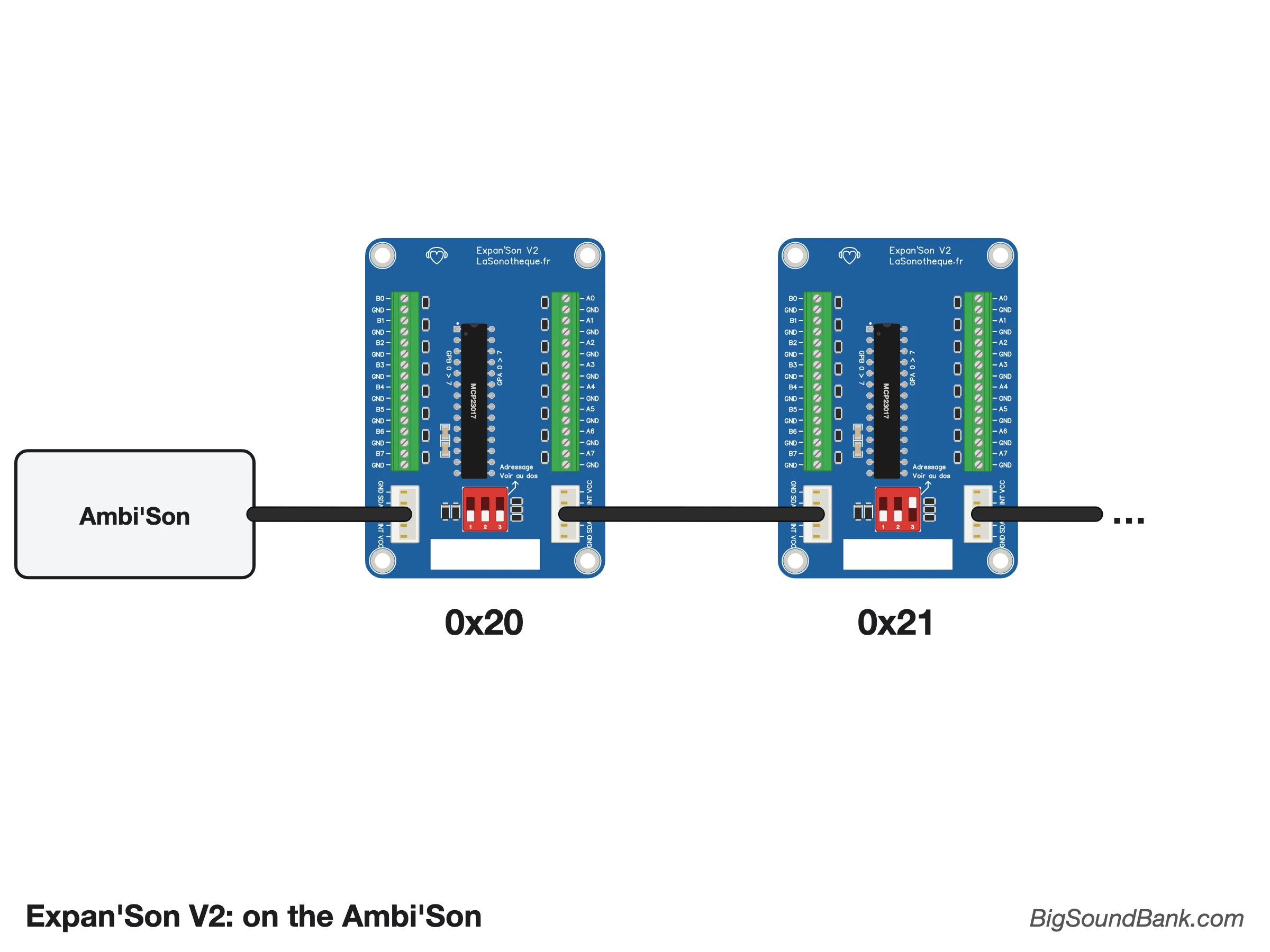
- Wiring: the ribbon cable links the Ambi'Son's "I2C Option" connector (from V14 onwards, if the option was chosen) to one of the two connectors 1 of the first board. Another ribbon cable goes from its second connector to the next board, and so on.
- Nothing to add: the Ambi'Son powers the boards and already has the resistors the bus needs.
- The files: the board set to address 0x20 plays files 1 to 16, the one set to 0x21 files 17 to 32, and so on up to 0x27 (files 113 to 128). What counts is the address, not the board's position on the cable. The boards are detected automatically at start-up.
- The program: tell me when you order the Ambi'Son that you will use Expan'Son boards, and I will set up its program for you. With the program supplied, they work as inputs only (buttons, contacts); to light LEDs or drive relays, the Nano's program has to be adapted.
- Installation: the board has the Ambi'Son's format, with its holes in the same place. You can stack it above or below, with spacers, in whatever order suits you: the ribbon cable runs on one side or the other, and the slot 6 helps route the cables.
Setting the address
Each board connected to the same bus must have a different address, from 0x20 to 0x27. It is set with the three small switches 2 (ON is up, towards the chip), with no tools or soldering. The table is also printed on the back of the board.
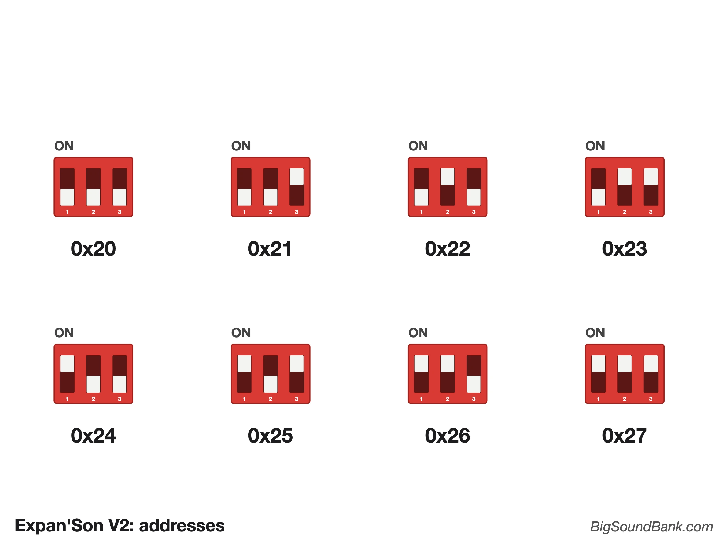
| Switch 1 | Switch 2 | Switch 3 | Address | With an Ambi'Son |
|---|---|---|---|---|
| OFF | OFF | OFF | 0x20 | files 1 to 16 |
| OFF | OFF | ON | 0x21 | files 17 to 32 |
| OFF | ON | OFF | 0x22 | files 33 to 48 |
| OFF | ON | ON | 0x23 | files 49 to 64 |
| ON | OFF | OFF | 0x24 | files 65 to 80 |
| ON | OFF | ON | 0x25 | files 81 to 96 |
| ON | ON | OFF | 0x26 | files 97 to 112 |
| ON | ON | ON | 0x27 | files 113 to 128 |
On an Expan'Son V1, which has four switches, the address is set the same way with switches 2, 3 and 4. Its switch 1 connects pull-up resistors to the bus: leave it OFF with an Ambi'Son, which already has its own, and ON on a single board (the first one) with an Arduino alone.
Connecting the channels
Each channel has two terminals: the channel itself (B0 to B7, A0 to A7) and its ground (GND). A wire stripped by 5 to 6 mm slides into the side of the terminal block and is clamped by the screw on top.
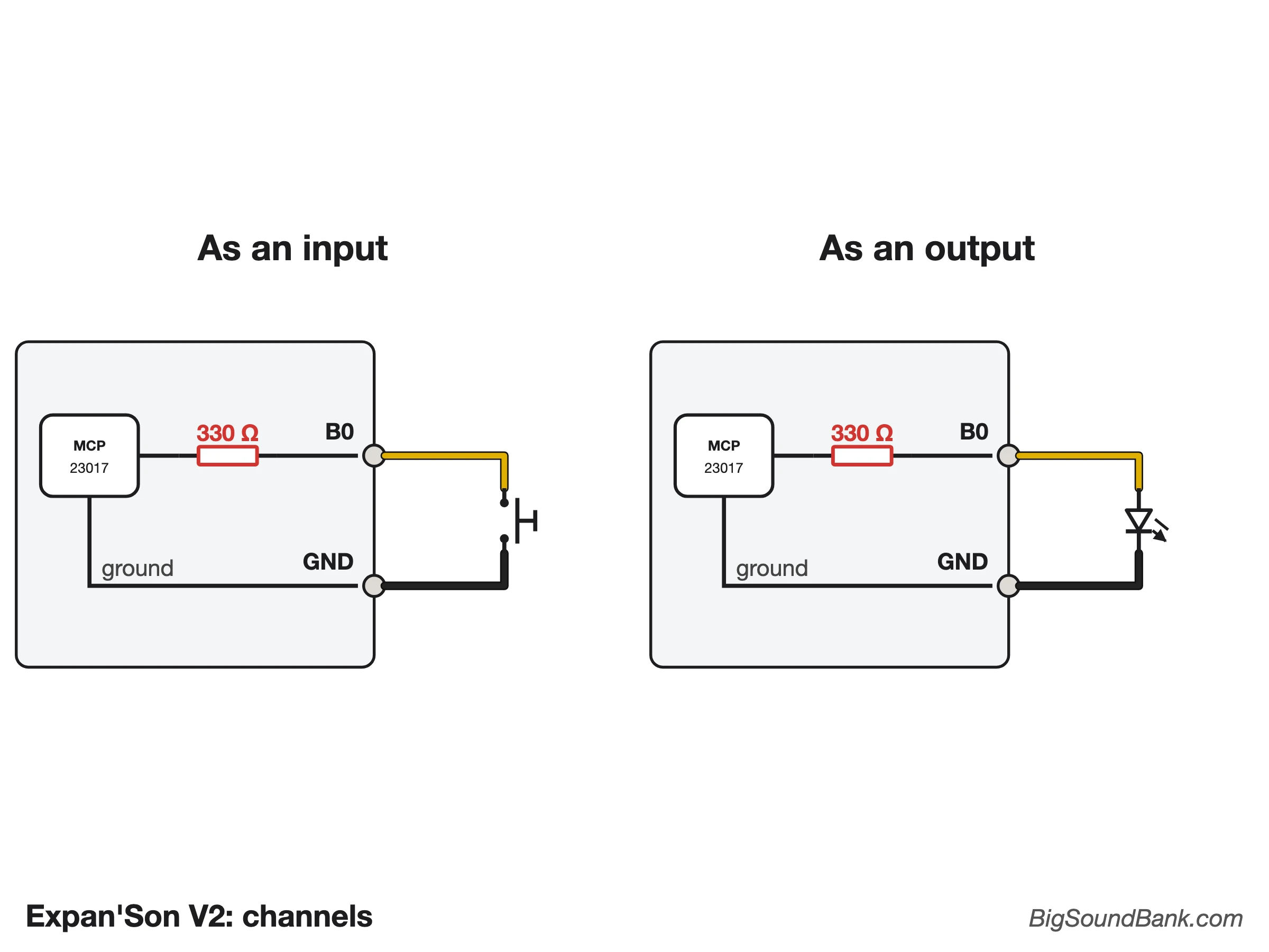
- As an input (button, switch, contact, on/off sensor): connect it between the channel and GND. The program enables the chip's internal pull-up resistor: the channel reads 1 at rest and 0 when the contact closes.
- As an output (LED): the LED's + leg (the longer one) on the channel, the other on GND. The 330 Ω resistor is already on the board, nothing to add: count about 10 mA per LED at 5 V, a little less at 3.3 V (the LED is then slightly dimmer).
- Current: 150 mA at most for the whole board, all channels together. Do not light 16 LEDs at full power at the same time.
- To control something heavier (relay, motor, LED strip, bulb, solenoid valve): do not draw the current from the board. The channel only gives the order, to a relay module, a transistor, a MOSFET or a ULN2803-type chip, which supplies the current.
- You can mix inputs and outputs on the same board, for example 12 buttons and 4 lamps, or 8 illuminated buttons (the button on one channel, its light on another).
With an Arduino, an ESP32 or a Raspberry Pi
The Expan'Son works with any board that speaks I2C, independently of my audio players. Find the I2C pins of your board:
| Board | SDA (data) | SCL (clock) |
|---|---|---|
| Arduino Uno / Nano | A4 | A5 |
| Arduino Mega | 20 | 21 |
| Arduino Leonardo / Micro | 2 | 3 |
| ESP32 | GPIO 21 | GPIO 22 |
| Raspberry Pi | GPIO 2 (pin 3) | GPIO 3 (pin 5) |
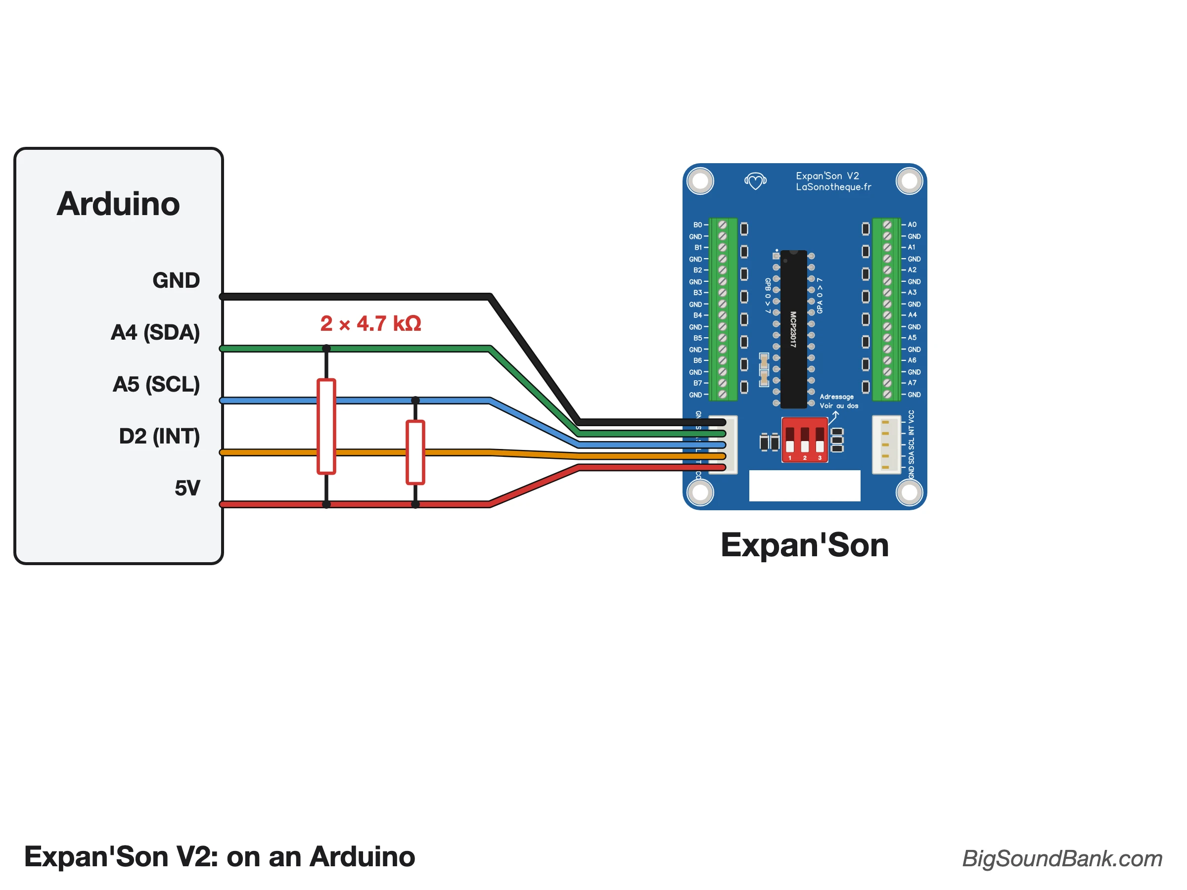
- Power supply: connect VCC to your board's voltage, 5 V for an Arduino Uno, Nano or Mega, and always 3.3 V for a Raspberry Pi (or any 3.3 V board): its pins do not tolerate 5 V.
- Bus resistors: the I2C bus needs two resistors that pull SDA and SCL up to VCC, once for the whole bus, not one per board. A Raspberry Pi already has them. With an Arduino or an ESP32 alone, add two 4.7 kΩ resistors: one between SDA and VCC, the other between SCL and VCC.
- Address: enter in your program the address set on each board (0x20 to 0x27).
- The INT wire (optional): instead of polling the boards all the time, your program can be notified as soon as an input changes: the INT wire then goes to 0. Connect it to a free pin (for example D2), set as an input with internal pull-up (
INPUT_PULLUP). The INT wires of all the boards can safely be linked together.
For programmers
- The MCP23017 is driven with the Arduino
Wirelibrary, or with a ready-made MCP23017 library. - The back of the board shows the setting ODR=1 (INT output as open drain): recommended, but the board is protected even without it, thanks to a diode on the INT wire. The V1 also reminded MIRROR=1: essential on the V1, where only one of the chip's interrupt outputs is wired; on the V2, both are, so this setting no longer changes anything.
- Leave INTPOL at 0, its factory setting (interrupt when INT goes to 0).
- Because of the diodes, the INT wire only goes down to about 0.5 V. This is no problem for an Arduino; on a Raspberry Pi or an ESP32, keep the internal pull-up or a 10 kΩ resistor on INT, nothing stronger.
Problems, Solutions & Ideas
- A board is not detected: check that no two boards have the same address, that the ribbon cable is pushed fully in, and, with an Ambi'Son, that its program is set up for Expan'Son boards.
- Wrong readings, or buttons that trigger by themselves: with an Arduino alone, the two bus resistors are probably missing. With an Ambi'Son and an Expan'Son V1, check that its switch 1 is OFF.
- On a V1, only channels A0 to A7 signal through the INT wire: set MIRROR=1 in your program.
- The LEDs are dim: this is normal at 3.3 V; at 5 V, choose high-efficiency LEDs.
- For any other question or idea, contact me.
Versions
- May 2024 - prototype: buttons and LEDs on an MCP23017, for the Cadavre Exquis Sonore.
- 2026 - V1: first board, 50 × 75 mm, one mounting hole. Four switches: switch 1 connects pull-up resistors to the bus, switches 2, 3 and 4 set the address.
- Late 2026 - V2: the exact format of the Ambi'Son (55 × 78 mm, four mounting holes) and a slot for the cables. No more pull-up resistors on the board (they are on the Ambi'Son, and the board stays universal), so only three address switches. A diode on each of the chip's two interrupt outputs: no more need for the MIRROR setting. Terminal blocks aligned along the sides.
Conclusion
Connecting an Expan'Son is really simple, but at the risk of repeating myself: feel free to contact me if you have any questions or suggestions about it!